The Mystery of the Iron Bridge
BBC Time Watch
October 2001, shown early 2002.
Contact us01484 428203Casting Process
This is purely for an academic and historic record. By request we have adopted 18th Century production techniques to produce the castings and by recording observations of the process we are able to offer the theorists proof and reasons for the defects and casting flow patterns that are plainly visible on the original structure at Ironbridge.
During open cast pouring the rate of cooling is accelerated, as the heat loss to the air is greater than in an enclosed mould. We know the iron contracts at 1:100. i.e. 1 mm in every 100 mm. The flow of the metal over the mould quickly reduced the metal temperature. The diagram shows the x-section of the mould as it cools. Red being the first to cool and yellow the last. Observations show a surface crust bridges over the casting, this crust was visible as the mould was still being poured with the solidified top being carried on the molten metal beneath. The greatest heat loss in the mould is at the corners and then along the edge. We observed the surface forming a meniscus above the edge of the casting. This we presumed was the weight of the molten iron in the centre of the casting forcing the already frozen sides to be pushed up the edge.
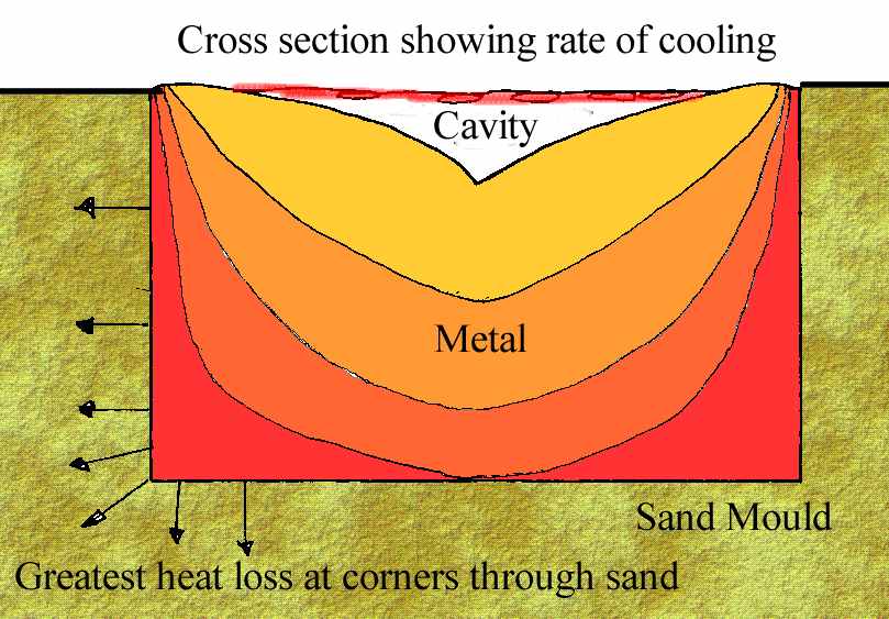
Cast Iron rate of cooling
The cavity appears under the crust as the iron shrinks on cooling, leaving the original crust bridging the top. Holes clearly visible on the surface and the rounded edges are seen to support this.
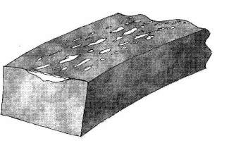
Cavity beneath iron crust
When we cast these we were aware that in the 18th Century Darby would have been able to cast the ribs in the middle reducing the distance the molten iron would have to travel. The originals were 66 feet long and ours 33 feet. To see if it was possible to run this distance we cast the first rib from one end, the centre of the arch end. The casting ran slowly but smoothly. We were very much aware of the iron cooling as it travelled the distance. This observation is obvious as we can see the change in colour as the white hot metal cools through yellow and then orange as the temperature loss starts to show.
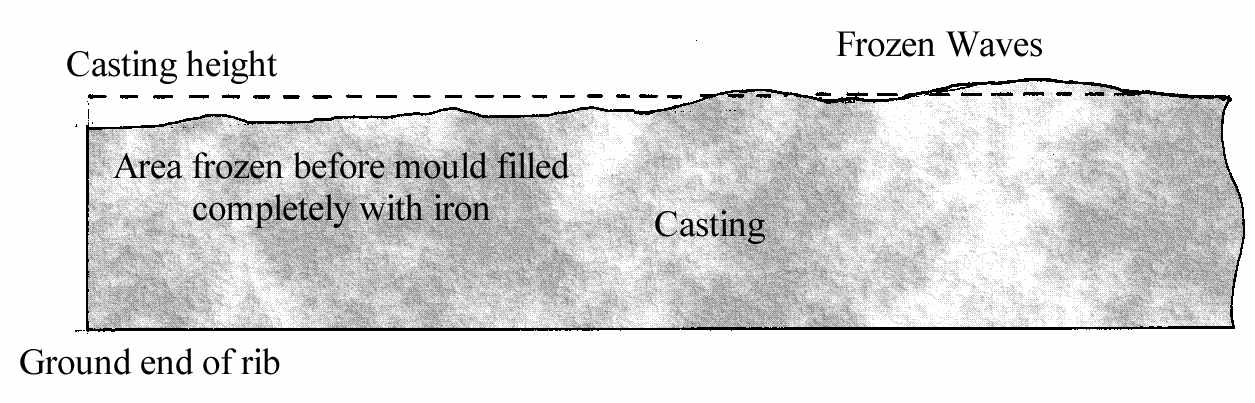
We then decided we would try and cast the metal faster as the iron had barely reached the 33 feet before it had started to solidify. This brought about other problems the main one being the turbulence of the liquid iron. As the iron hit the ends the backwash was forming waves about 25 mm high, these were running up and down the casting and because the mould was cast open would have spilt over the top if casting continued at the start rate. We slowed to a trickle until the waves had subsided, this however had the effect of cooling grabbing hold of the far end and freezing the action into the casting. Where the waves formed they have been captured by the solidification of the metal at the furthest point away from where we were pouring.
Metal x-section
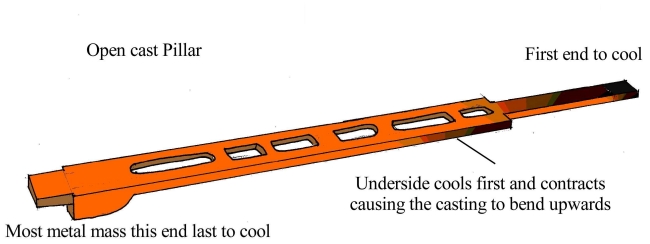
Whereas the rib was of one section we were aware that contraction would be uniform and in one direction. The pillars on the other hand were irregular, with a large base at one end and a much thinner section at the other. There are bends in the original, which we were keen to see why. We decided this was more than likely due to the different cooling rates along the length. It was reasoned that if we were to throw sand over the open casts as they cooled it may even out the cooling/contraction and bending. The bending would occur, as each part of the casting from the bottom of the mould up would cool. Remember that this metal contracts and becomes shorter as it freezes thus the bottom face shortens and pushes the top upwards. Bearing this in mind we cast all six of the pillars and covered three of them with dry sand to allow them to cool more uniformly. The other three were left to cool naturally. The difference between the two is obvious with the uncovered castings showing about 30 mm bends.
We also observed as the sand was thrown on the casting it sometimes broke the surface crust, which left these areas higher where the force of the sand had crumpled/scabbed the surface by folding the skin that had formed on cooling.
Rate of molten iron cooling
To enable historians to analyse the same defects, holes etc. that are found on the original, the castings were made as in the 18th century hence the visible and pitting on the surface which was the top of the casting exposed to the air.
This is not representative of the quality of castings produced in our foundry today using modern methods and technology.
Replicated 18th Century casting process created similar defects found in the original ironwork
Project Team
- Producer
- Deborah Perkin - BBC Wales
- Historic Adviser
- David de Haan - Ironbridge Gorge Museum
- Project Engineer
- Jamie Hillier - Buro Happold
- Erection Team
- Royal Engineers, 51 Squadron (Air Assist) Led by Lt. Ben Day
- Iron Castings
- Nigel Downs - H.Downs & Sons Ltd Huddersfield
- Ironwork Technical Drawings
- Bill Blake - English Metric Survey Team Heritage
- Structural evaluation
- Andrew Smith
- Site Management
- Alex Medhurst - Ironbridge Gorge Museum
- Abutments/site support
- Staff - Blists Hill Victorian village
Technical
Ironwork
The original ribs were cast in 2 pieces joining at the centre, each half weighing 5.75 tons. At half scale, they weigh only 15 cwt (680Kg). The span of 1 arc is 50feet (15.24m) and the chord length of each rib was 37 feet (11.3m). In the uprights holes would allow other parts of the bridge to be slotted in place.
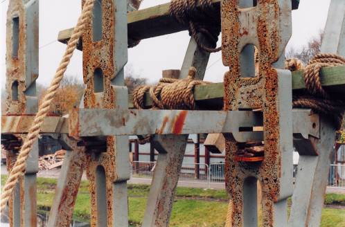
Scaffold
The timber poles used for erection are 33 feet (10m) high, though the original scaffold poles would have stood in the river Severn and must have been nearly 70 feet (21.3m). They acted as derricks (cranes) and the frame may have been moved to a new position for each rib.
Ropes
Only hemp ropes were used to build the model,hauled by teams of soldiers. Some ropes have since been replaced by steel cables for safety. A trial lift of a 5 ton weight using the scaffold, hemp ropes and pulleys required 25 people to raise it from the ground.
Abutments
The original abutments are in stone, not brick as shown here, they provide support for the base plates. Only the middle 3 base plates out of a set of 5 have been used, these are only 1" (25mm) thick, unlike the originals which were 4" (100mm).